F60 TC wood‑gas CHP
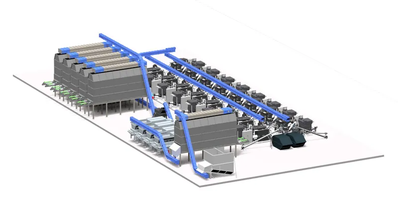
Turbocharged, modular and built in Austria. One unit delivers 80 kW electricity, 158 kW heat and around 25 t of biochar a year from about 1.5 t of wood chips per day.
- 80 kWelectrical output (net)
- 158 kWthermal output
- 28 %electrical efficiency
- ~91 %fuel efficiency incl. biochar
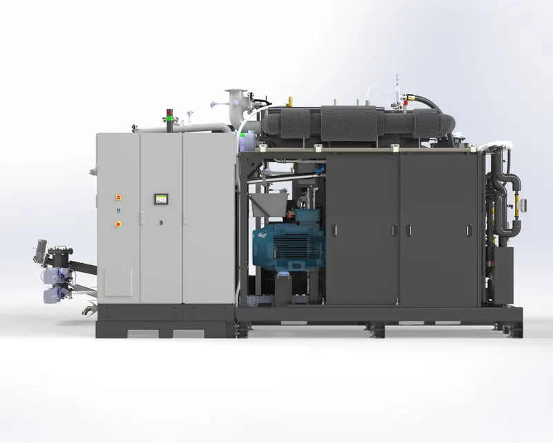
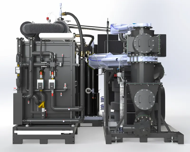
Inside an F60 TC
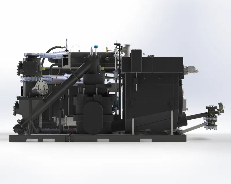
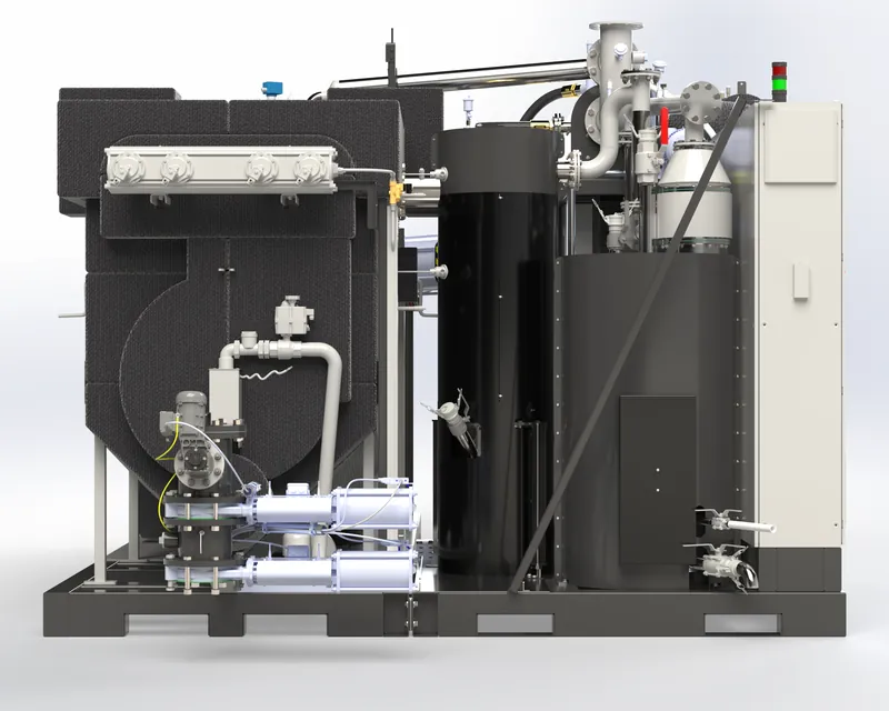
From wood chip to kilowatt-hour in a closed, automated process – with heat recovered at every step. Select an assembly to see what it does. The pictures are the same ones our customers see in the FLOYD control system.
Simplified from the FLOYD process and instrumentation diagram. Numbers match the areas in the FLOYD HMI.
What each assembly does
Eight assemblies work as one plant. A single control system with the FLOYD HMI starts, runs and monitors them together – from the fuel feed to the heat meter.
 01
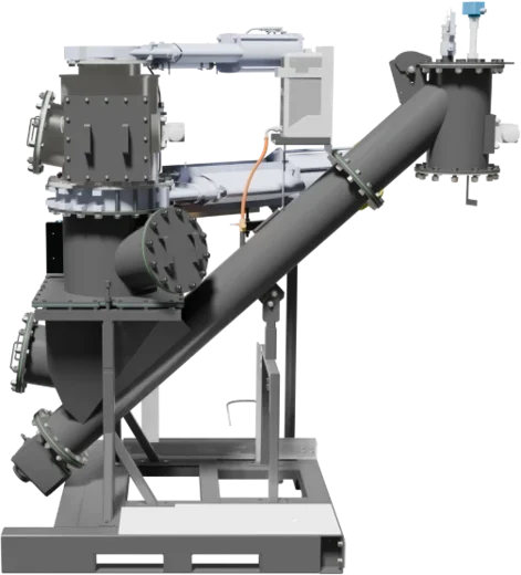
Fuel supply
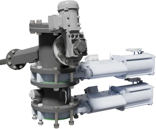
Responsible for: A steady, metered fuel feed and a gas-tight separation between fuel store and reactor.
Wood chips arrive from the day bin in a feed hopper. Level sensors call for fuel only when it is needed. Two motorised shut-off valves work as an airlock, so no air gets into the gasifier and no gas gets out. A screw then feeds the chips into the top of the gasifier.
 02
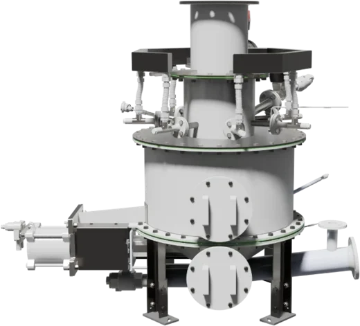
Gasifier
Responsible for: Converting the wood into a combustible wood gas of stable quality.
In the fixed-bed gasifier the wood reacts with a precisely dosed amount of air. Instead of burning, it is converted into a combustible gas – mainly carbon monoxide, hydrogen and methane. A stirrer and a vibrator keep the bed loose and even; an electric air heater is used for the start. Temperatures and pressures are measured continuously and the air supply is adjusted automatically.
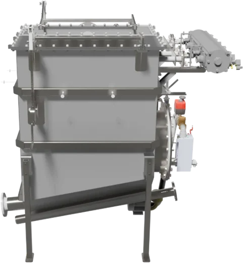 03
Hot-gas filter
Responsible for: Clean gas for the engine and the separation of the biochar.
The hot gas flows through ceramic filter candles. Dust and the biochar carried out of the gasifier stay on the outside of the candles, while the gas is still hot enough that tars remain in the gas phase instead of condensing. Short compressed-air pulses clean the candles automatically. The separated biochar collects in the filter hopper – this is the only point where biochar leaves the process.
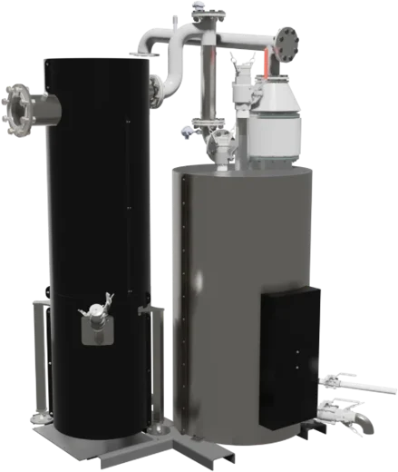 04
Gas cooler and safety filter
Responsible for: Cooling the clean gas to engine-intake temperature and protecting the engine.
A heat exchanger cools the clean gas with the heating water – this is one of three heat-recovery stages. Cooler gas is denser, so the engine gets more energy per stroke. A final safety filter then catches anything that could reach the engine; condensate is drained off.
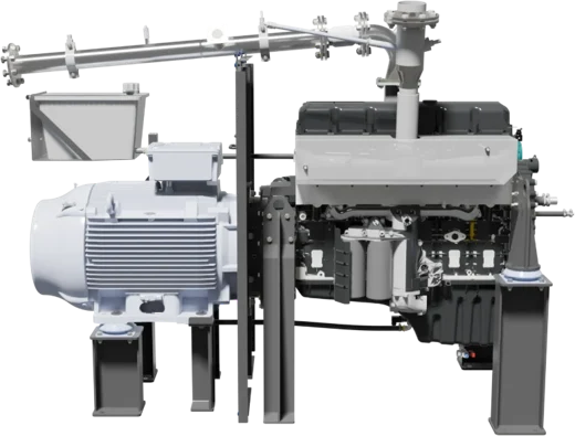 05
Gas engine and generator
Responsible for: Turning the wood gas into electricity – synchronised with your grid.
The gas is mixed with filtered combustion air and burned in a gas engine. Lambda, ignition and throttle are controlled continuously, so the engine runs cleanly at changing gas quality and load. The engine drives a generator that delivers three-phase electricity at 400 V. Output modulates with your demand.
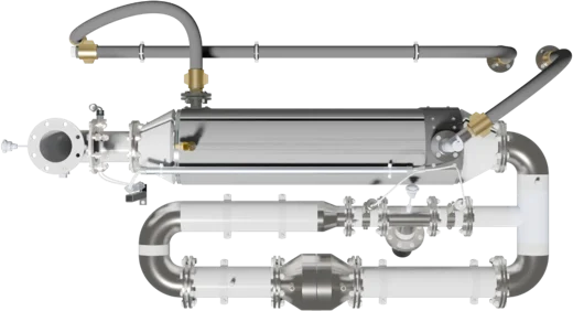 07/08
Catalyst and exhaust heat exchanger
Responsible for: Clean exhaust and recovery of the exhaust heat.
Behind the engine a catalytic converter cleans the exhaust gas. An exhaust heat exchanger then takes the remaining heat into the heating water – the last and hottest heat-recovery stage – before the cooled exhaust leaves through the stack.
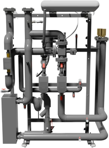 06/09
Hot-water hydraulics
Responsible for: Engine cooling, collecting all recovered heat and delivering it at a constant temperature.
The return water from your heating system first cools the engine, then the product gas and finally the exhaust gas – so it gets hotter at every stage. Pumps and a mixing valve keep the flow temperature constant, and a heat meter records the delivered energy.
 10
Biochar discharge
Responsible for: Continuous, gas-tight removal of the biochar from the process.
A screw conveyor takes the biochar from the hot-gas filter into a closed collection bin. Level sensors trigger the discharge automatically, and the bin is emptied through a valve into your container. With more than 90 % carbon the biochar is a product in its own right – for soil, feed or carbon-removal certificates.
Which biomass can you use?
The F60 TC runs on more than forest chips. What matters is a dry, free-flowing fuel of the right size.
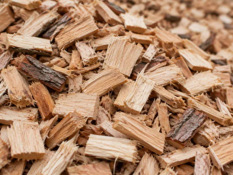
Symbol photo Forest wood chips
Particle size 5–60 mm.
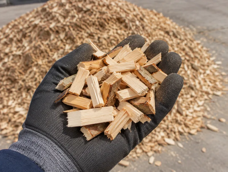
Symbol photo Waste wood
Slowly shredded and screened, pieces up to about 6–7 cm.
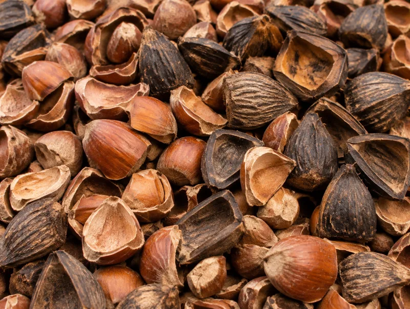
Symbol photo Nut shells
Palm kernel shells (PKS), hazelnut shells and others.
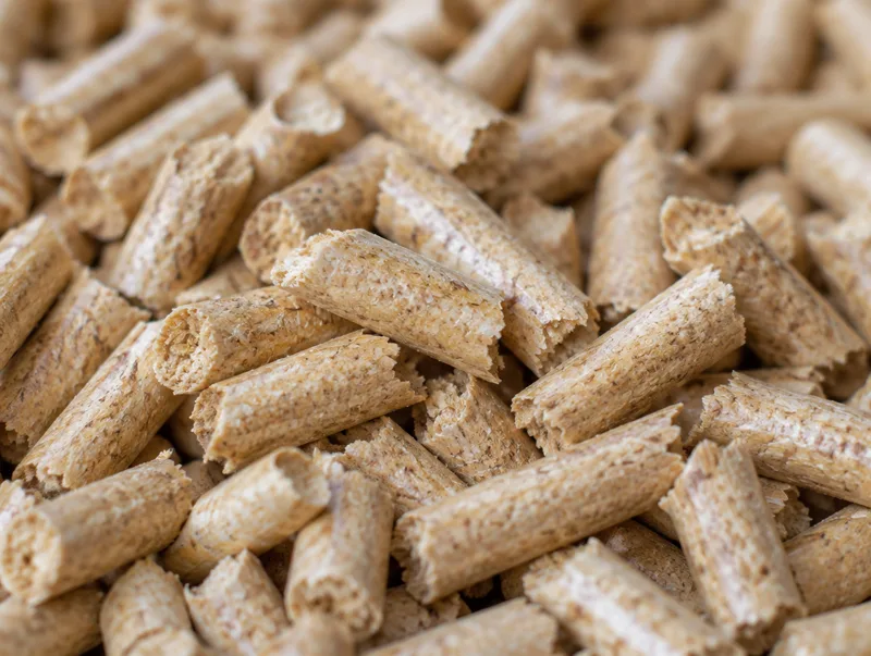
Symbol photo Wood pellets
Standard wood pellets.
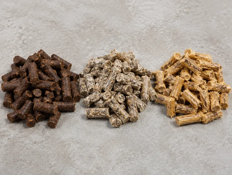
Symbol photo Special pellets
Coffee grounds, mushroom substrate, wood–straw blends and more.
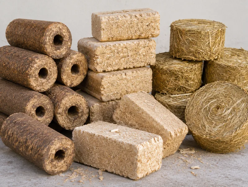
Symbol photo Briquettes
Different types of briquettes. For use in the F60 TC they must first be broken into smaller pieces.
We support fuels with up to 15 % water content (full rated output up to 10 %). Not sure about your biomass? Tell us what you have and we will check it. →
Performance
| Electrical output (net) | 80 kW |
|---|---|
| Thermal output | 158 kW |
| Electrical efficiency | 28 ± 1 % |
| Thermal efficiency | ~55 % |
| Fuel thermal input | approx. 288 kW |
| Fuel efficiency (electricity + heat) | ~83 % |
| Fuel efficiency (incl. biochar) | ~91 % |
| Annual electricity | approx. 656 MWh |
| Annual heat | approx. 1,296 MWh |
| Annual biochar | approx. 20.5–25.4 t |
| Power modulation | down to approx. 45–50 kW |
Fuel and consumption
| Fuel | Wood chips per FLOYD wood-chip standard |
|---|---|
| Water content | up to 15 % supported; max. 10 % for full rated output, above that with reduced output |
| Particle size | 5–60 mm, no sawdust, fines < 10 % |
| Wood-chip consumption | approx. 62.5 ± 2 kg/h |
| Biochar output | ~4–5 % of input mass, 2.5–3.1 kg/h |
| Engine oil | < 3 l/day, automatic refill |
Emissions
| NOx | < 250 mg/Nm³ at 5 % O₂ |
|---|---|
| CO | < 650 mg/Nm³ at 5 % O₂ |
| Dust | < 10 mg/Nm³ |
| Exhaust temperature | < 150 °C after heat exchanger |
| After-treatment | three-way catalyst; options: oxidation catalyst or EGR |
| Noise | < 71 dB(A) at 1 m |
Technology
| Gasifier | Fixed-bed downdraft, automatic ignition and biochar discharge |
|---|---|
| Gas cleaning | Two-stage filter system, ceramic hot-gas filter |
| Engine | 6-cylinder in-line, turbocharged, flexible speed |
| Generator | Asynchronous, grid feed-in via ABB four-quadrant converter |
| Grid functions | Power control, power-factor control, reactive power, fault-ride-through |
| Control | Beckhoff industrial control, 4G connectivity |
Connections
| Electrical (IEC) | 400 V, 3-phase, 50–60 Hz, 200 A |
|---|---|
| Electrical (UL/CSA) | 380–500 V, 3-phase, 50–60 Hz, 200 A |
| Heating flow / return | max. 95 °C / 45–65 °C, 4.5 m³/h, DN50 |
| Wood-chip inlet | DN300 slide gate |
| Biochar outlet | DN200 slide gate |
| Exhaust | DN150 |
| Compressed air | min. 80 l/min at 8 bar |
Dimensions and installation
| Length × width × height | 6.1 × 3.6 × 2.9 m |
|---|---|
| Weight | approx. 8.6 t |
| Footprint | approx. 55 m², plus 1.5 m service area |
| Ventilation | 5,000 m³/h at 25 °C outdoor temperature |
| Ambient temperature | 5–40 °C |
| Lead time | approx. 6 months after order |
| Commissioning | by FLOYD, approx. 6–12 man-days |
Safety
| Negative-pressure system | In case of a leak, air is drawn in – wood gas cannot escape |
|---|---|
| CO monitoring | Pre-installed, calibrated CO detector |
| Fire protection | Quench tank floods the feed line on backfire |
Values per unit at rated load and 8,200 h/a with wood chips per the FLOYD wood-chip standard. Projected turbo-operation values; thermal and fuel efficiency pending final validation. Not binding – the offer applies.
Clean exhaust – without AdBlue
Most engine CHPs need an SCR system with continuous urea (AdBlue) dosing to meet NOx limits – one more tank, pump and consumable to look after. The F60 TC reaches the limits with catalyst technology alone: no urea, no refills, low-maintenance, stable and reliable.
- No SCR, no urea injection, no consumable to refill – low-maintenance
- Three-way catalyst, stable above 600 °C
- Modular catalyst element – quick to change, minimal downtime
- Official measurement at Carrosserie Zumbrunn: NOx below 100 mg – without AdBlue
Three levels – chosen for your limit values
- CO conversion
- > 95 %
- NOx conversion
- > 90 %
- CO conversion
- > 85 %
- NOx conversion
- > 95 %
- CO conversion
- > 95 %
- NOx conversion
- > 98 %
Conversion rates of the catalyst system. The emission values in the data sheet apply.